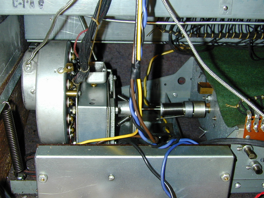
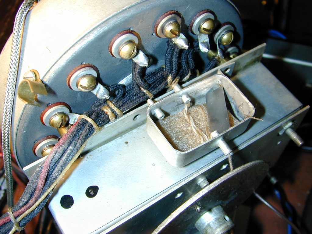
Facing the rear of the B2, the vibrator scanner is attached to the Run motor of the organ. From the left: the small and large flat cylinders are covers for the scanner itself. The smaller cylinder contains three bushings that contact a small pin on the back of the rotor. BE CAREFUL AND DON'T BEND THE PIN OR THE BUSHINGS after you take the cylinders! The silver-colored braided wire is the scanner's audio output, which goes to the organ's preamp. The bundle of black, blue (yes, they're blue) wires and red wire go to the vibrato switches' terminals, and the vibrato line box. The smaller rectangular box is the Run motor, with the oil cup on top. The short springs in the middle of the photo couple the run motor to the shaft of the tone generator. (The Start motor is on the opposite end.) The larger box in the foreground with two nuts and a screw house the motors' and Start/Run switches' terminals. The large spring on the left is one of several that suspends the tone generator within the cabinet of the organ.
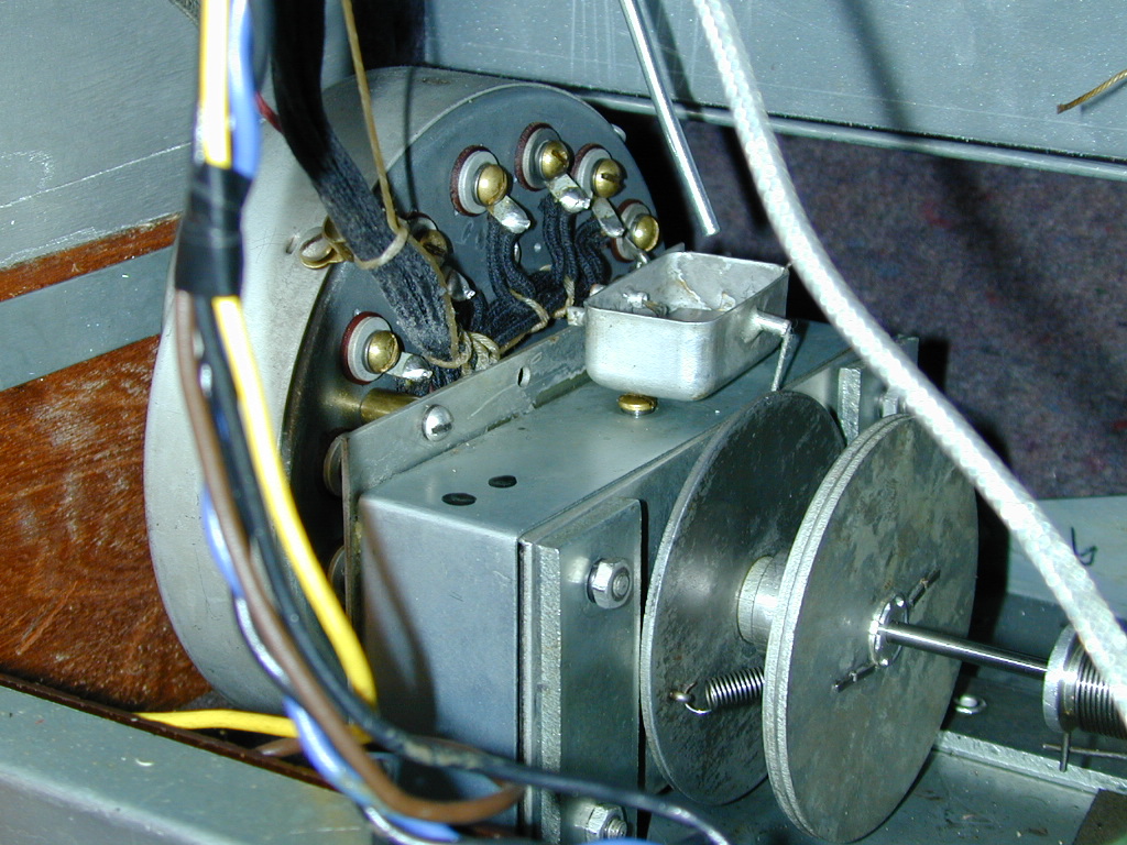
Another view. Note the wicks from the oil cup. They route down to the various spinning shafts.
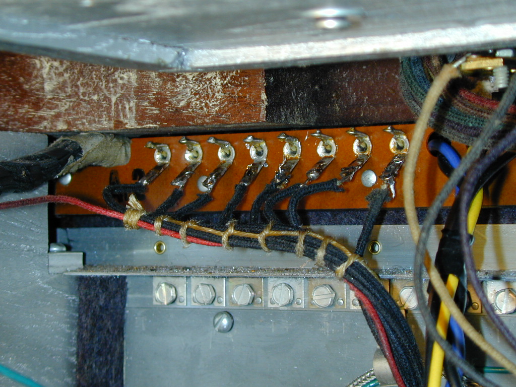
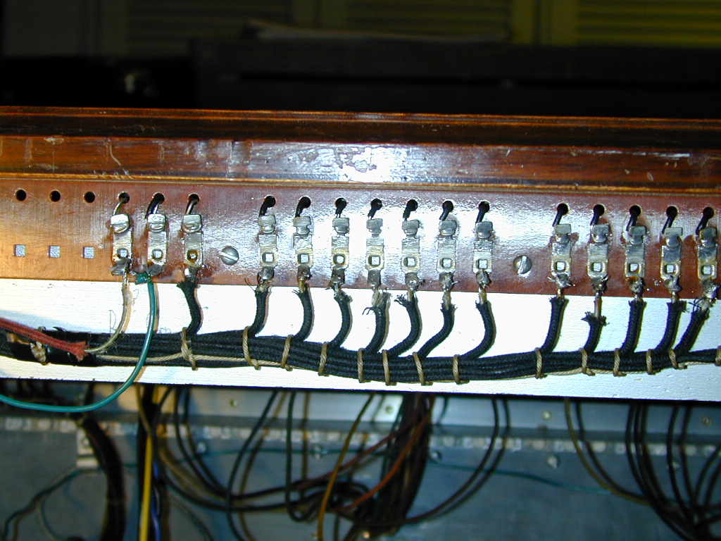
Vibrato switch terminals. These eight black and blue wires are unsoldered, in order to remove the scanner assembly.
Vibrato line box terminals. Only the red wire is unsoldered, in order to remove the scanner.
Detail of oil cup and scanner wiring terminals. Each of sixteen terminals is unscrewed. Note the order the hardware is applied: brass screw, lock washer, wire terminal, orange insulating washer, then the scanner housing. On the inside, there's another square insulating washer, then a brass stator. Don't bend or compress the six layers of the stators!
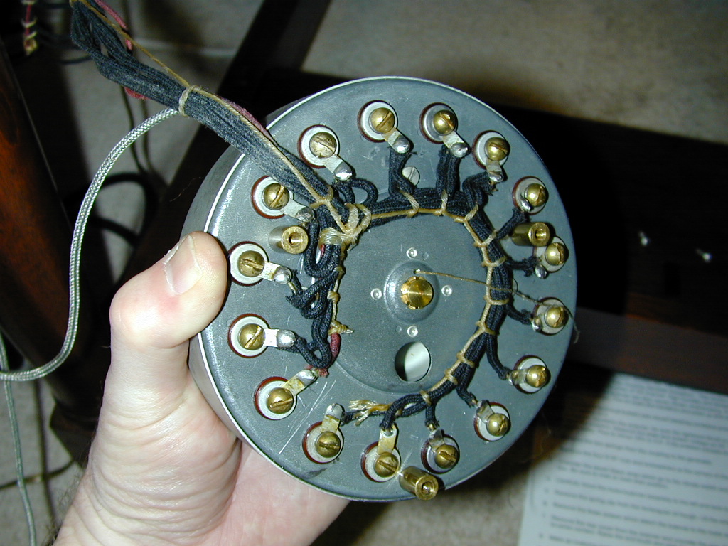
The scanner, removed. The hole below center is where the shaft from the Run motor goes; it engages a gear inside the scanner to turn the rotor. Note the oil wick as it leaves a tiny hole above the brass rotor bearing at the center. Opposite the bearing on the back of the rotor is the small pin with three bushings, as mentioned before. Note the red wire terminal, about 8:00. A former owner had already serviced this scanner; they made an index mark for the red wire.
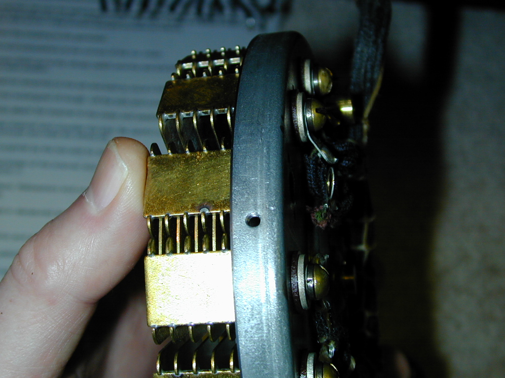
Inside detail showing the stators. I was carefully supporting it with my thub. Again, don't bend the stators! The inside of the scanner was pretty clean, however the black/blue/red wiring bundle was quite oily, as were the brass screws, washers and insulators.
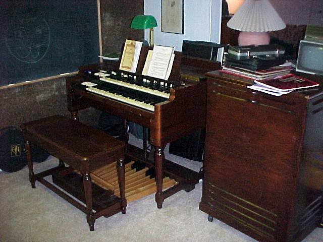
Our early 1950s Hammond B2 and matching Leslie 122 tone cabinet. The main electronic difference between this and a B3 is the lack of percussion. I added a Trek II TP-2B percussion unit, which was also a simple installation.